Datasheet4U Logo Datasheet4U.com

ABE0102 - (ABE0101 - ABE0106) Low EMI Spread Spectrum Multiplier Clock

Download the ABE0102 datasheet PDF. This datasheet also covers the ABE0101 variant, as both devices belong to the same (abe0101 - abe0106) low emi spread spectrum multiplier clock family and are provided as variant models within a single manufacturer datasheet.

General Description

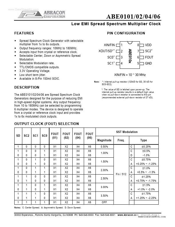
The ABE0101/02/04/06 are Spread Spectrum Clock Generators designed for the purpose of reducing EMI in high-speed digital systems.

Any output frequency from 10 to 180MHz can be selected by programming 6 multiplier modes.

Key Features

  • Spread Spectrum Clock Generator with selectable multiplier from 1x to 6x outputs. Output frequency ranges: 10MHz to 180MHz. Accepts input from crystal or reference clock. Selectable Center, Down or Asymmetric Spread Modulation. Selectable Modulation rate. TTL/CMOS compatible outputs. 3.3V Operating Voltage. Low short term jitter. Available in 8-Pin 150mil SOIC. PIN.

📥 Download Datasheet

Note: The manufacturer provides a single datasheet file (ABE0101_AbraconCorporation.pdf) that lists specifications for multiple related part numbers.

Datasheet Details

Part number ABE0102
Manufacturer Abracon Corporation
File Size 243.78 KB
Description (ABE0101 - ABE0106) Low EMI Spread Spectrum Multiplier Clock
Datasheet download datasheet ABE0102 Datasheet

Full PDF Text Transcription (Reference)

The following content is an automatically extracted verbatim text from the original manufacturer datasheet and is provided for reference purposes only.

View original datasheet text
www.DataSheet4U.com ABE0101/02/04/06 Low EMI Spread Spectrum Multiplier Clock FEATURES • • • • • • • • • Spread Spectrum Clock Generator with selectable multiplier from 1x to 6x outputs. Output frequency ranges: 10MHz to 180MHz. Accepts input from crystal or reference clock. Selectable Center, Down or Asymmetric Spread Modulation. Selectable Modulation rate. TTL/CMOS compatible outputs. 3.3V Operating Voltage. Low short term jitter. Available in 8-Pin 150mil SOIC. PIN CONFIGURATION XIN/FIN XOUT/SD*^ SC0^ SC1^ 1 8 VDD SC2^ FOUT GND ABE010x 2 3 4 7 6 5 XIN/FIN = 10 ~ 30 MHz Note: ^: Internal pull-up resistor (120k Ω for SD, 30 k Ω for SC0-SC2). *: The value of SD is latched upon power-up.